Adjusting the Cable On Renegade Hoof Boots
For Cable Change video, go here —>Cable Change Video
For info on changing a cable go here —>Cable Change Page
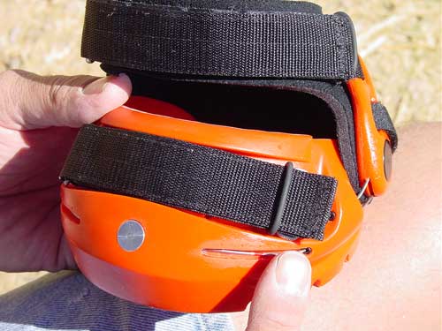
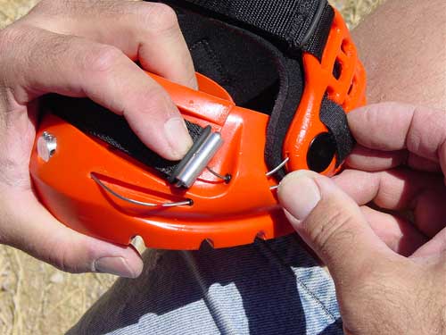
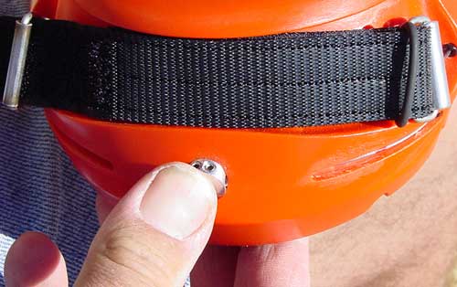
When the boot is installed upon the hoof, and with the toe strap properly tensioned as explained on the Installing the Boot page, the preferred amount of strap extending past the black rubber keeper loop is from 1/2" to 3/4" like shown in the photo above.
If the strap extends less than 1/2", then the strap is prone to being pulled loose when riding in deep footing or heavy brush.
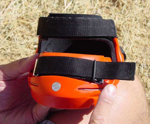
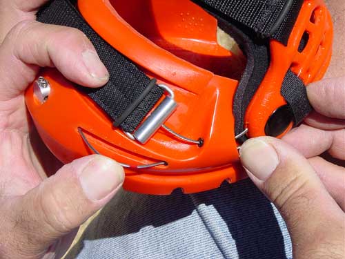
If the strap extends past the loop more than 3/4" as shown in the photo below, the contact surface area of the gripping portion of the strap will be reduced. This can lead to a reduction in the holding power of the strap.
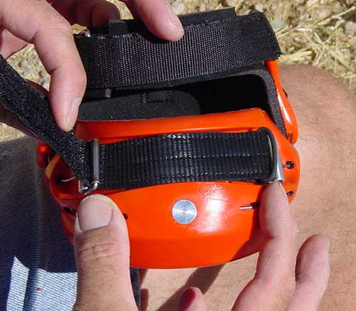
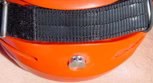
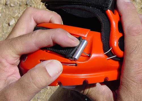
Correspondingly, the gap between the Cable Adapter (the cylindrical, shiny, aluminum part that connects the cable to the Tension Strap) and the Lateral Cable Guide Block (the protrusion on the side of the boot shell that has two holes in it) should also be at least 3/4". If this gap is less than 1/2" then it may be difficult to be able to easily pull the Heel Captivator well up onto the heel bulbs. Worse yet, under extreme load they may interfere with each other, changing the angle of engagement, loading the cables individual strands unevenly resulting in failure of overloaded strands, followed by the rest of the strands.
Additionally, make sure that when you initially tighten the strap, you are doing so based on feel and not on any goal as to where you want the end of the strap to be. In other words, don't pull the strap extra tight or make it extra loose in order to comply with the recommended end position specifications.
The strap will end up where the strap ends up based solely on the amount of force you use to tension it as described in the Installing the Boot page. If the strap end-position is out of parameter then proceed with the cable adjustment sequence below.
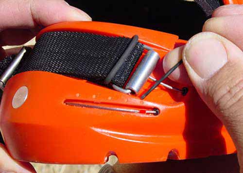
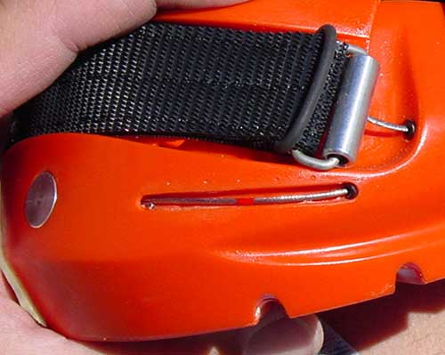
Notice the Marker Dimples on the boot and the red Paint Dot on the cable. These will be your reference marks for making the adjustment. Moving the cable toward the cable clamp will effectively shorten the cable setting and reduce the amount of strap end length and vice versa.
The Cables are designed so that if necessary, a cable adjustment outward can be performed even to the extent that the Paint Dot on the cable can only just barely be visible as it disappears into the Lateral Cable Guide Block.
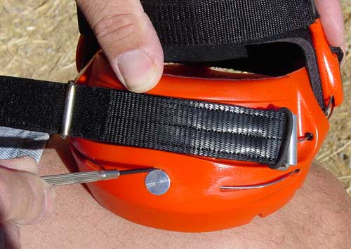
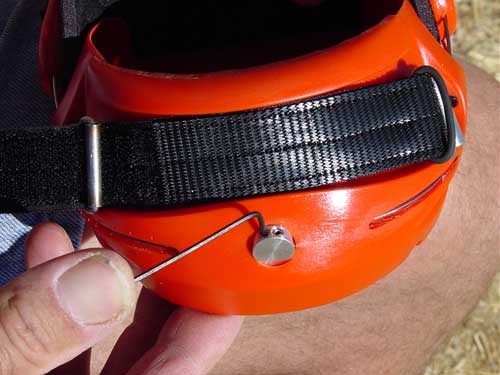
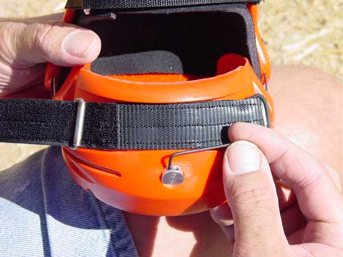
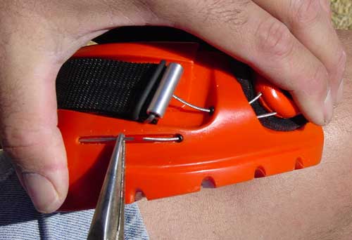
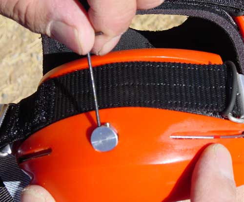
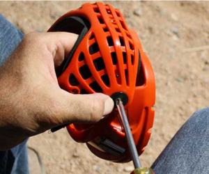
Using a small flat screwdriver or other pointy tool, pry out the cable clamp just enough to expose the top edge like shown below. New Method: Since these photos were taken, the Cable Clamp has been updated with an "easy pry" hole on the exposed face of the Cable Clamp. To use, simply stick the long end of the supplied L-wrench into this hole and rotate the L-wrench down, consequently also rotating the top of the Cable Clamp outward to expose the set screws.
Using the supplied 1/16" L-wrench or a purchased Pro Hex wrench, back the set-screws out about 2-1/2 full turns which in most cases is sufficient to release the cable for adjustment. Leaving the set screws in place like this reduces the risk of losing these small screws and can save time. However, this will not allow the Cable Clamp to rotate back into its original position and at times will not allow the cable to move easily if at all. This is due to the offset between the Cable Clamp Cable-Guideway and the Boot Shell Cable-Guideways which can pinch the Cable. To avoid this, it is recommended to remove the set screws completely, save them in a cup so as not to lose them, and rotate the Cable Clamp fully back into its original position. This will ensure the Cable will slide smoothly without binding.
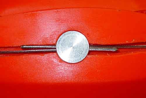
For the sake of clarity, I have cut away part of the boot material to expose the hidden cable pathways and the cable ends. Visible are the two individual cables (one from the left side and one from the right side) which overlap each other at the cable clamp.
In order to shorten the effective length of each cable, you will be resetting the end of each cable by pushing the end further through the cable clamp or vice versa. Another view is shown below.
Another cutaway view.
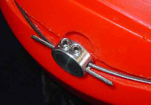
Adjust as necessary and repeat for the other side. In most cases, the cable will only need to be moved one or two marks. If you need to move the cable three marks or more, this is an indication that you may need a different size boot.
Should you have trouble moving the cables as demonstrated above, remove the set-screws entirely and push the cable clamp back into it's home position as previously discussed in step 7. This will allow the cables to have their maximum looseness so be extra carefull not to pull the cables out. If you accidentally pull the cables out, review the Cable Change Page.
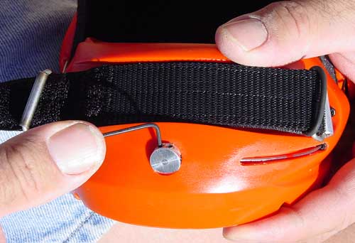
The picture does not show this but it is best to rotate the Cable Clamp out a full 90 degrees so that the set screws are facing directly outward. This will best ensure that the Cables lay side by side relative to the set screws so that the set screws apply pressure evenly between each of the two cables. Now re-tighten the set screws but do this by tightening one screw a little bit then the other screw a little bit, back and forth a few times. In this way you will seat the cables under the screws more evenly than just cranking them down in one step.
Be sure to tighten the set screws well. Insufficiently torqued set screws may result in the boot base becoming detached from the Heel Captivator en route, possibly even never to be seen again. When tightening, you should be able to feel the resistance increase slightly as the set screws make contact with and begin to compress the cables. Continue about 1/2 to 1 more turn until you feel the set screws stop when the cables are just about fully compressed. Apply just a tad more torque to each set screw to be sure they are snug.

